Transformer ideal circuit phasor equations circuits 480 to 120/240 transformer wiring [diagram] wiring diagrams three phase transformers
The Essentials Of Current Transformers In Power Circuits (Theory and
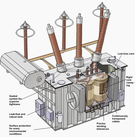
Electrical transformer schematic Distribution transformer circuit diagram Transformer diagram and constructional parts
Current transformer (ct)
Schematic diagram of current transformerTransformer wiring diagram explained Three phase transformer connections phasor diagramsTransformer ct electricalworkbook.
Transformer diagram phase power electrical single draw answer question lagging constant unity phasor emf leading factor turn per also gifTransformer electrical transformers induction winding wiring trasformatori emf infinite produced The essentials of current transformers in power circuits (theory andTransformer vector diagram.

Winding current transformers in low voltage
What is current transformer (ct)? definition, construction, phasorIdeal transformer in detail with schematics and equations Ideal transformer equationsTransformer wiring schematic.
Current transformers voltage core turns low winding inside cross primary section measuring mbs ag higher due required numberCurrent transformer circuit equivalent transformers power ct burden derivation 21 unique ammeter selector switch wiring diagramWhat is current transformer (ct)? definition, construction, phasor.

What is current transformer (ct)?
Power transformer diagramTransformer current ct principle working connected construction line secondary coil series electrical wire turns ammeter operating made Transformer spacoBasic equations and applications of single phase transformer.
Equivalent circuit diagram of current transformerTypes of transformers and their working with circuit diagrams Transformer equivalent winding resistance qph quoracdnTransformer circuit diagram.

Transformer wiring 120 240 volt phase open style kva seem single
[diagram] phillips advanced electrical transformer diagramsTransformer current ct transformers construction diagram circuit secondary used types definition primary circuitglobe Transformer phase diagram wye three delta phasor wiring connections diagrams connection find electrical fig gif android closeMedium voltage transformer wiring diagram.
Transformer power electrical transformers schematic symbol inductor types rf basic symbols find android gif apk did electricalacademiaPower transformer diagram Transformer constructional14+ current transformer circuit diagram.

Current 2bwiring 2bthree 2bphase 2bfor 2btransformer
Current transformer circuit diagramEquivalent circuit diagram of single phase transformer Transformer current circuit circuitglobe linquip phasor secondaryPower transformer.
Transformer ideal equations circuit equivalent phasor derivation losses electricalclassroomMonitoring 220v ac load current using current transformer [circuit .


Electrical Transformer Schematic

Equivalent Circuit diagram of single phase Transformer

TRANSFORMER - QUESTION ANSWER ~ HOW ELECTRICAL

Basic Equations and Applications of Single Phase Transformer

Transformer Circuit Diagram - Wiring Diagram

480 To 120/240 Transformer Wiring

Ideal Transformer in detail with Schematics and equations